29+ 3 entity relationship diagram
The diagram is exported. For example the elements writer novel.
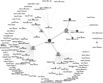
Wet Paper Between Us New Reading Methods Part Ii The New Walt Whitman Studies
In an ER Diagram entities are the most important parts.

. Entity-Relationship model модель сущность связь модель данных позволяющая описывать концептуальные схемы предметной области. This is the next installment in a series of articles about the essential diagrams used within the Unified Modeling Language or UML. Decentralized identifiers DIDs are a new type of identifier that enables verifiable decentralized digital identity.
ER-модель используется при высокоуровневом концептуальном. Entity-relationship diagrams are incredibly useful and you can easily create one of your own by following these simple steps. In my previous article on sequence diagrams I shifted focus away from the UML 14 spec to OMGs Adopted 20 Draft Specification of UML UML 2In this article I will discuss Structure Diagrams which is a new diagram category that.
This will be fairly complete if the database builder has identified the foreign keys. A DID refers to any subject eg a person organization thing data model abstract entity etc as determined by the controller of the DID. An Entity Relationship Diagram ERD is a visual representation of different entities within a system and how they relate to each other.
A many-to-one mapping means that many instances of this entity are mapped to one instance of another entity many items in one cart. This allows for simplified editing using Inkscape or other vector image editor. From either the Entity Relationship or Object Relational stencil drag an Entity shape onto the drawing.
There are many tools that are more sophisticated than MS Access for making diagrams on a larger scale. Binary Relationship with 11 cardinality with total participation of an entity. In contrast to typical federated identifiers DIDs have been designed so that they may be decoupled from centralized registries.
To export in a vector format use To PDF File instead. One to one When each entity in each entity set can take part only once in the relationship the cardinality is one to oneLet us assume that a male can marry to one female and a female can marry to one. The ManyToOne annotation lets us create bidirectional relationships too.
As we have seen in section 2 we can specify a many-to-one relationship by using the ManyToOne annotation. Click File Data Modeler Print Diagram To Image File. Thank u this was very big help for us.
ER Diagrams are most often used to design or debug relational databases in the fields of software engineering business information systems education and research. Entity-relationship diagrams ERD are essential to modeling anything from simple to complex databases but the shapes and notations used can be very confusing. Using code-first entity migrations as is done in this project enables the database tables and their properties including their relationships to be defined in code.
Browse to and select the export file location. An Entity Relationship ER Diagram is a type of flowchart that illustrates how entities such as people objects or concepts relate to each other within a system. The classes for the data entities form the Object side of the Object Relational Mapper ORM that is Entity Framework.
In this article we will discuss how to convert ER diagram to Relational Model for different scenarios. Perhaps the simplest is the Relationship Diagram that MS Access can produce from a completed database. Lucidchart is the leading ER diagram tool.
This guide will help you to become an expert in ER diagram notation and you will be well on your way to model your own database. Entities are typically nouns such as car bank student or product. After designing the ER diagram of system we need to convert it to Relational models which can directly be implemented by any RDBMS like Oracle MySQL etc.
These instructions may work for SQL Developer 320923 to. Double-click the shape to open the Database Properties window. Under Categories click Definition and type a name for the table.
The number of times an entity of an entity set participates in a relationship set is known as cardinality. Use the Entity shape to create a table in your diagram. Cardinality can be of different types.
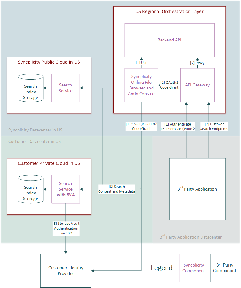
Syncplicity Api Portal

Information Engineering Style Cardinality Erd Relationship Diagram Information Engineering Diagram

Google Ai Blog May 2021
Entity Relationship Diagram Erd What Is An Er Diagram Relationship Diagram Diagram Erd

Chen Style Cardinality Erd Relationship Diagram Diagram Relationship

Art Gallery Database Management System Er Diagram 34 Pages Explanation In Doc 1 9mb Updated Learn With Jordan

An Entity Relationship Diagram Showing A Structured Approach To Defining A Metadata Information Architecture Software Architecture Design Relationship Diagram

Er Diagram Of Movie Theatre Relationship Diagram Diagram Interactive Design

Pin On Software Development Entity Relationship Diagram Erd

Pin On Er Diagrams
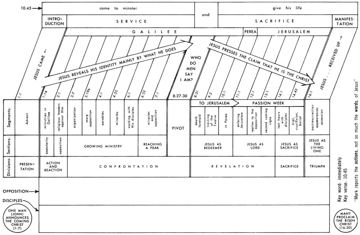
Mark 2 Commentary Precept Austin

Edward Snowden An Astrological Analysis
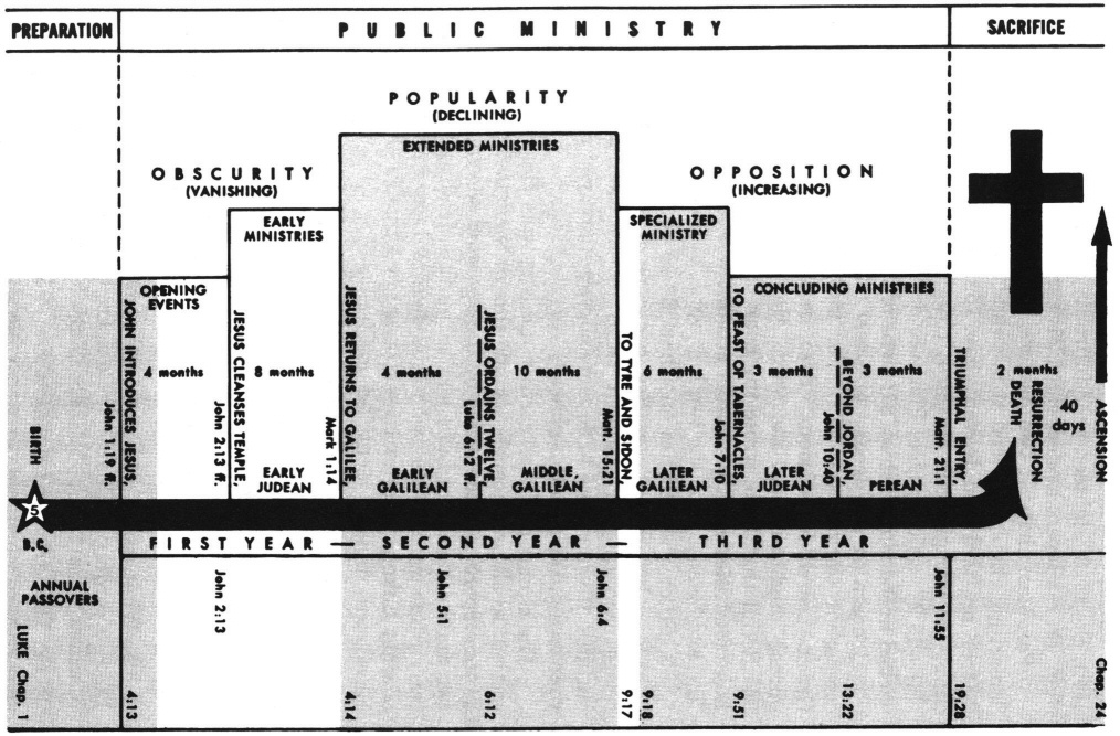
Luke 4 Commentary Precept Austin
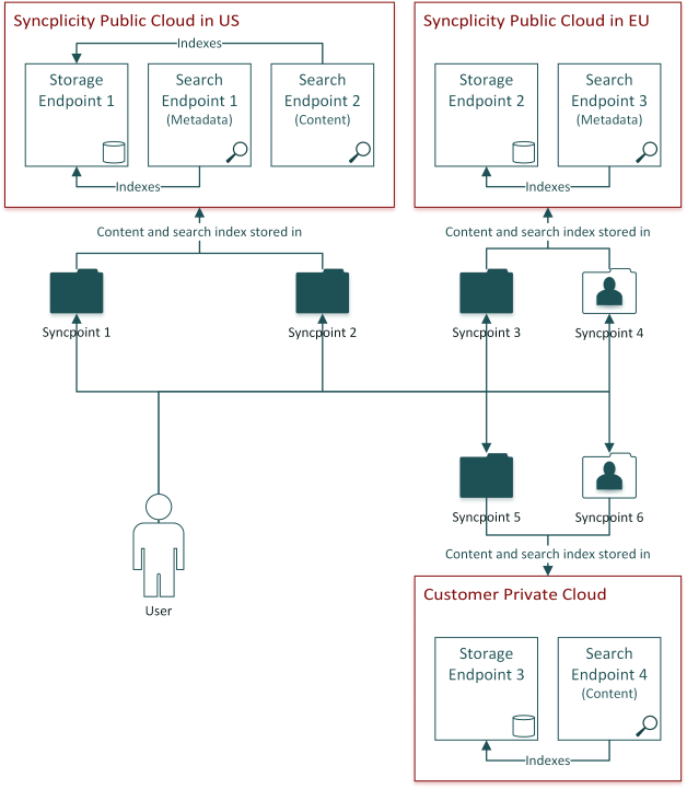
Syncplicity Api Portal
2

Tm226390d3 425img027 Jpg
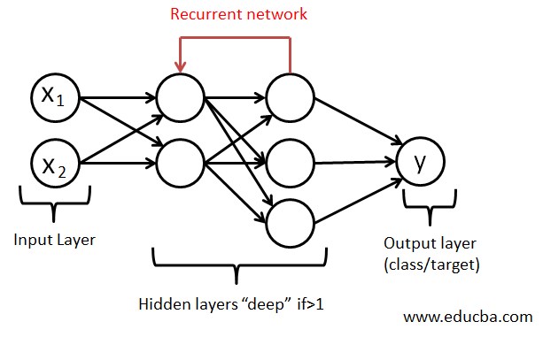
What Is Neural Networks How It Works Advantages Scope Skills